
How to Use an Armada Pro900 Underground Wire Locator
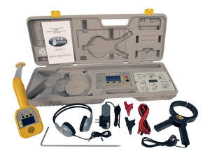

To use an Armada Pro900, choose a locating method that suits the cable, prepare the connections according to the unit's manual, match the receiver to the transmitter mode, and follow a repeatable signal along the route. The critical skill is interpreting that signal without mistaking interference or poor coupling for a cable fault.
This guide explains the workflow for landscape and irrigation service technicians. It accompanies the Armada Pro900 user guide, Rev. 09/23 (PDF); it does not replace training or the instructions supplied with your equipment. See the Pro900 product page for the listed kit.
Before starting: isolate the target and identify your version
For direct connection, de-energize and verify the target is not live, and disconnect equipment that could be affected by the locator signal—including controllers, transformers and connected electronics. The transmitter can produce hazardous voltage even when the system being traced is low voltage. Make or change clip connections only with the transmitter off, and never touch energized clips.
Do not connect the test leads to live power wiring. Work near energized equipment requires qualified personnel and the applicable operating procedure. Locating is not permission to excavate: obtain the required utility markings and arrange private-line locating where needed before digging or driving a ground stake.
Check the model label, controls, leads and power requirements. Armada's currently linked manual is marked Rev. 09/23; newer product information describes additional power options. Use only power equipment approved for your particular unit. If the controls or accessories differ, resolve that with the manufacturer before following a setup sequence.
1. Choose direct connection, clamp, broadcast or passive AC
| Method | What it does | Important limitation |
|---|---|---|
| Direct connection | Applies the tracing signal to an isolated target conductor through the leads | Requires safe access and the correct return path |
| Inductive clamp | Couples a signal into an accessible cable without a bare-conductor clip connection | The manual requires grounding on both sides of the clamp |
| Broadcast | Induces a signal from the transmitter case into nearby conductors | May couple to more than one conductor |
| Passive AC | Listens for power-frequency signals using the receiver alone | Cannot establish that an area is clear of cables or that a cable is safe |
The Pro900 supports 2 kHz and 33 kHz direct signals, with separate inductive and passive operation. A useful way to plan the job is to write down which method you intend to use and why. This prevents a mode change in the field from becoming an unrecorded change in what the result means.
2. Prepare a direct-connect trace
After isolation and with the transmitter off, connect the red lead to the target conductor and the black lead to the ground stake as directed in the manual. Position the stake away from the transmitter and perpendicular to the expected route. Inspect the complete setup before enabling the output.
Follow the manual's LO-F or HI-F output procedure. If LO-F cannot obtain the specified OK indication, turn the transmitter off and revisit the ground connection. Increasing output is not a substitute for correcting an incomplete tracing circuit.
3. Match the receiver and establish a repeatable route
Select the matching locating mode on the receiver. Then use controlled side-to-side sweeps to establish the route and mark it as you progress. Keep a record of the chosen mode, starting point and places where the response changes.
For each suspected segment, ask: does the response repeat when approached again, and does the route remain consistent with the last reliable mark? A single loud tone is less useful than a repeatable path. Do not move directly from an uncertain signal to excavation.
4. Understand null versus peak
In null tracking, the response falls over the conductor and becomes stronger to either side. In peak tracking, the strongest response is over the conductor. Where both are supported, comparing their indicated positions helps expose an uncertain trace. Do not assume both are available in every connection mode: the linked manual specifies null reception for clamp and broadcast operation.
Practice these responses on a known, safely isolated test route before relying on them on an unfamiliar site. Label your marks by confidence rather than making every tentative reading look like a confirmed cable location.
5. Account for inductive-method limitations
A clamp needs an appropriate current loop; simply putting it around a disconnected conductor does not guarantee a trace. Follow Armada's grounding and clamp-placement instructions. Broadcast operation can energize several nearby conductors, so a received signal alone does not identify the cable.
Move outside the transmitter's direct field before interpreting a broadcast response as a buried route. The manual describes roughly 20–25 feet of nearby interference from the case itself. This is a setup consideration, not a guaranteed clearance distance for every site. Repositioning the transmitter and confirming that the route remains consistent can help distinguish a useful result from a misleading one.
6. Troubleshoot a weak or confusing signal
- Little or no response: check the selected modes, power condition, connections and return path before deciding the cable is broken.
- Unstable reception: inspect batteries and leads, reconsider grounding and look for nearby conductors that could carry the signal.
- A sudden signal change: mark the location for investigation. A branch, loop, valve, connection or damage may require further checks.
- A suspected small insulation fault: a dedicated GFL3000 ground fault locator may be more appropriate than continuing to increase the route-locator output.
Armada's Pro900 troubleshooting guidance highlights grounding, batteries and competing signals. Keep these setup checks separate from your diagnosis of the installed wiring.
Can the Pro900 find a broken wire or sprinkler valve?
It can help locate severe wire damage and connected irrigation solenoids, but neither a disappearing signal nor a broad response proves the exact fault or valve identity. Follow the manufacturer's valve-locating procedure and independently confirm the target. See what wire locators, ground fault locators and TDRs can find for the limits of each instrument.
Does passive mode prove there are no buried power lines?
No. A power cable may not produce a detectable signal at the time of the scan. Passive reception cannot verify absence of voltage, identify every underground utility, or replace required utility-locating procedures.
Finish with documentation, not just paint marks
Record the equipment version, mode, connection point, route and unresolved areas. Shut down and disconnect the test equipment before restoring the system according to its instructions. For a lighting problem, return to electrical troubleshooting to verify the repair rather than treating the trace itself as proof of a working circuit.
Choosing equipment? Read Pro300 vs Pro700 vs Pro881 vs Pro900 or browse Armada diagnostic tools.
References and manual
Reviewed November 9, 2026. Use the Armada Pro900 user guide, Rev. 09/23 (PDF), Armada inductive-locating application note, and current Pro900 manufacturer information. Operating instructions supplied with your exact unit take priority.
- Jenny Branch